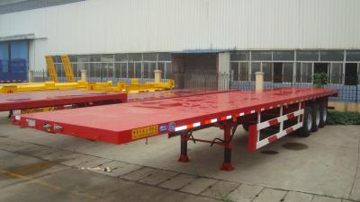
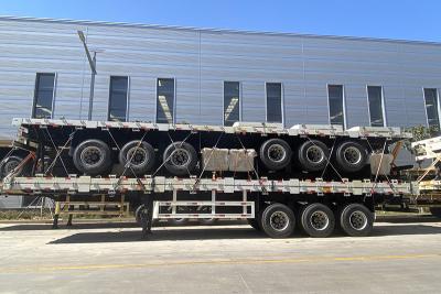
Self inspection specification for semi-trailer departure procedure operation
1. Pipeline laying and installation
A. Arrange the pipeline reasonably according to the vehicle model. The long pipe shall be connected with the air storage tank of the rear relay valve. The length shall be appropriate and shall not be too loose or tight. The pipe clamp shall be locked on the thread clamp screw on the right side of the longitudinal dye. The thread clamp shall not be missed. The pipeline that runs through the channel steel shall be installed with a thread breaking anti abrasion rubber ring at the channel steel wire hole
B. The lamps installed on the left and right side lamp holders are symmetrical and in the same direction. The branch line hole is equipped with wire passing rubber rings. The through branch line is connected with the side lamp through the longitudinal beam wire passing hole from the branch line clamp. The positive and negative pole wire ends are connected correctly without virtual connection. The mounting screws are tightened to ensure that there is no looseness. The rear tail lamp fog lamp .The number plate lamp shall be fully assembled, reasonable and effective.
C. When the pipeline is connected with the brake air chamber, the length of the air pipe shall be appropriate, the rivet head screws shall be used together with the short connector, the threads of the short tapered pipe connector shall be wrapped with raw material tape, and the threads shall be wrapped three to five turns in the direction of the thread to ensure that the screws are tightened without air leakage. The split system shall be connected with the brake air chamber of the relay valve to ensure that the pipeline is arranged smoothly without dead bends, and the middle position of the pipeline which cannot be fixed due to the large number of pipelines, Bind the adjacent pipes together with binding strips to support each other, and do not contact with any parts.
2. Accessory assembly
A. The nameplate is installed 200 mm from the side beam on the right side. First, check that the identification on the nameplate is correct, the handwriting is printed clearly, the font size is arranged in accordance with the regulations, and there is no sign of alteration. Drill holes on the front side beam with an electric drill, fix the connection with rivets, and do not deflect.
B. Triangular reflector shall be installed at the designated position of the rear bumper, and shall be fixed firmly and symmetrically with screws, without deflection and looseness, and the surface shall be free of oil stains and paint stains.
C.When installing the air hose quick connector and the seven hole circuit plug, the locking screw of the air hose quick connector shall be tightened without deflection and looseness, the wire of the circuit plug shall be connected correctly without virtual connection and short circuit, the insertion screw shall be connected firmly and reliably, and the accessory parts shall be complete and effective.
3 . Lighting and brake commissioning
A. Use a special wrench to adjust the adjusting arm bolt on the axle, adjust the brake shoe to contact the brake drum, and then back 3-4 grids. When the ventilation reaches 637-735kpa, check all pipe joints for air leakage. When simulating braking, all components should work. It is normal without clamping stagnation, and all lamps are in good working condition with correct indication.
B. All marking lamps shall be consistent with the markings of the tractor, and the semi trailer marking lamps installed shall be effectively controlled by the tractor. Ensure that the lines of all lamps are reliably connected, well contacted, correctly and reasonably installed, and the overall arrangement is beautiful.
4. Installation of traction head saddle and platform side protection
A. If the traction head needs to be equipped with saddles according to the contract requirements, the traction saddles and accessory accessories must be obtained according to the model marked on the dispatch list, and installed reasonably at the height specified in the dispatch list. The fixing bolts are 18x50. Grade 8.8 standard bolt set, torque 170-190N. M. The flat pad shall be tight and flat. It is strictly prohibited to make welding points and craters on the frame of the tractor head. The assembly procedure shall meet the technical requirements to ensure that the accessory parts are complete
B. When assembling the platform and side protection, turn off the main power switch of the tractor to prevent damage to the electrical components of the tractor head. Drill holes on the tractor head frame with a magnetic base electric drill, connect the platform base with standard bolts, and connect the upper part with the working platform. The working platform is made of 3mm anti-skid steel plate, and reinforced with four folded C-shaped grooves or welded angle iron. The front edge is 0.8-1m from the rear end of the tractor head. It can be flexibly applied according to the vehicle model, It is not allowed to weld spot and accessory parts on the platform at will.
C. The side protection shall be reasonably, safely and effectively assembled. The operating valve rack and battery switch shall not be shielded on both sides. The upper horizontal and vertical scales shall be kept away from the oil tank mouth. All welded junctions shall be uniform and beautiful. All bolted connections shall be firm and reliable. The bolts shall be flat padded with spring pads for supporting use. Welding slag, spatter, dust, oil stains and grinding sharp burrs of all parts shall be removed.
5. Frame VIN number and tractor headlight brake test.
A. Carefully verify that the vehicle model is consistent with the nameplate identification number, the height and spacing of words are consistent with the regulations, and correct. Select the right one at the front of the frame. Determine the location, print the VIN code of 17 digits with the printer, and the handwriting shall be clear without reprinting, blurring or alteration.
B. The tractor head of the saddle shall be assembled, the dust and sundries on the traction disc of the saddle shall be removed, and an appropriate amount of lubricant shall be applied to connect the semi-trailer. The connection and separation shall be normal, and there shall be no open movement during forward and braking. The separation arm shall be smooth in and out.
C. The semi-trailer indicator lamp is consistent with the tractor head indicator lamp. Check whether the lamp is normal and effective. Check whether the lamp is running on the factory road with the vehicle. When braking at the initial speed of 30KM/H, check whether each tire brakes uniformly without front and rear lag. The braking force of the service braking should be evenly distributed between the left and right tires of the same axle in the longitudinal direction, without deviation. The braking distance should not be too dry for 9m. The sideslip deviation of the whole vehicle should not exceed a 3m wide testing channel to ensure that each valve slave cylinder works normally and effectively.


